IntelliVerter
By Control House
Giving intelligence to the common inverter
INSTRUCTIONS
The IntelliVerter is designed to operate in place of your inverter remote control. It will work with any inverter that allows a remote signal to turn it off and on using a contact closure. The IntelliVerter has a dry contact rated at up to 1 amp for this use. If the inverter uses a different type of remote such as a smart remote with serial or other type communication control, the IntelliVerter will not work unless the inverter also can be switched with some type of hardware remote port or ignition lockout. Below you will find a list of inverters known to be compatible. Keep checking as additional inverters will be listed as they are discovered.
| Table of known compatible inverters. | ||
| Manufacturer | Known Model #'s | Description of connections |
| WFCO | WF-5110HP | Connect using inverter remote port |
| Xantrex |
Freedom HFS (all models) PROwatt SW (all models) Freedom Xi (all models) Freedom HF (all models) Should work with any model with ignition lockout feature - see inverter manual |
Connect using INV terminals on IntelliVerter +12V to one INV terminal, the other INV terminal to the inverter ignition lockout wire. Some models may have the inverter ignition lockout available through the Xantrex remote. NOTE: You may need to purchase the proper inverter remote to use the IntelliVerter. |
| Samlex America |
PST-3000-12 Remote Port: Allowing the use of any 2 wire switch to turn the inverter ON and OFF. Ex. Toggle switch or light switch. - see inverter manual |
Connect using INV terminals on IntelliVerter |
| KISAE TECHNOLOGY | MW1210, MW1215, SW1210, SW1220 | Connect using inverter remote port |
| Cobra | All CPI model inverters | Connect using inverter remote port |
| Go Power |
GP-SW-150, GP-SW-300, GP-SW-600, GP-SW-1500, GP-SW1000, GP-SW2000, GP-SW3000, GP-HS1500 Works on any model with The Hardwire Remote Port: Allowing the use of any 2 wire switch to turn the inverter ON and OFF. Ex. Toggle switch or light switch. - see inverter manual |
Connect using INV terminals on IntelliVerter |
| Magnum Energy | ME
Series MS Series MSH-M Series MSH-RE Series MS-AEJ Series MS-E Series RD Series RD-E Series |
Connect using inverter remote port into Stack Port of the Inverter |
| AIMS Power |
PWRIG200012120S PWRIG300012120S PWRIG500012120S |
Connect using INV terminals on IntelliVerter to remote switch connector supplied with the inverter. See the inverter manual |
| AIMS Power |
PWRI100012S PIC100012120S PWRIX120012S PWRIX120012SC PWRINV1250W PWRIC150012W PWRI150012S PWRI150024S PWRI150048S PWRINV200012W PWRI200012120S PWRINV250012W PWRINV250024W PWRI300012120S PWRINV500012W PWRINV500024W PWRINV500036W PWRINV500048W PWRINV5K24012W PWRI5K22050 PWRINV8KW12V PWRI8K22050 PWRINV10KW12V PWRINV12KW24V |
Connect using inverter remote port |
| PowerDrive Inverters | RPPD1000, RPPD1500, RPPD2000 | Connect using inverter remote port |
| Outback Power |
FX2012T FX2424T FX3048T FVX2812 FVX3524 FVX3648 Any Model with remote switch control capability |
Connect using INV terminals on IntelliVerter See Owners Manual |
| Various - See Known Model column |
Works on any model with a Hardwire Remote Port:
Allowing the use of any 2 wire switch to turn the
inverter ON and OFF. Ex. Toggle switch or light
switch. - see inverter manual
|
Connect using INV terminals on IntelliVerter |
We are currently investigating the use of many other inverters.
In some cases to control the inverter, you must place it in the proper mode. The same mode required for the operation of the manufacturer's remote. See your inverter owner's manual for the description of remote operation.
Upon connection or power-up the IntelliVerter will go through an initialization process where all outputs will be turned off and timing cycles will be disabled. The IntelliVerter will place the timing mode in standard and all cycle bypasses will be placed in normal. When shipped the maximum time adjustment potentiometer is set to 60 minutes. Thus, the control will start with on and off cycle times at 60 minutes. The power switch is located on the left side of the IntelliVerter below the identified point on the faceplate.
The max time adjust potentiometer is located on the left side of the controller below the identified point on the faceplate. This is a mult-iturn potentiometer, which can be adjusted with a small standard screwdriver. Turning the potentiometer in the clockwise direction will increase the maximum time for the cycle. As you adjust this potentiometer you are automatically adjusting the off as well as the on time cycle length. The minimum time that will be allowed is 1 minute, the maximum is 166 minutes. The potentiometer is adjustable with 20 turns. If you have ordered no display, setting the potentiometer to 10 turns will set the timing cycle to around 80 minutes and so on. If you have the onboard digital display or the bluetooth option you will be able to see the actual maximum time value as you make the adjustment. You will also notice the time for the on time cycle will be displayed.
The IntelliVerter is supplied with BattStat which monitors the battery status of the RV. Voltage will be displayed on the onboard digital display or via the bluetooth option on your Android portable device.
Once powered, the IntelliVerter will remember the current status of timing modes, bypasses and so on. It will only return to the default mode when directed or powered down. Maximum timing modes will remain in tact since they are set with the max time potentiometer.
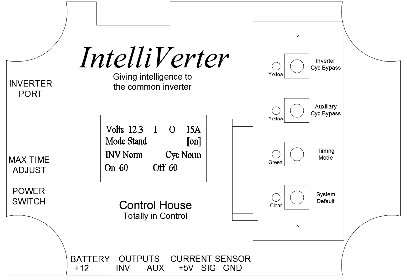
The IntelliVerter uses three types of input devices for control. These are dependent upon which model you have purchased. In any event, you will see that the operational procedures for each of these input devices are very much similar. The picture below shows an illustration of the IntelliVerter faceplate.
MOUNTING
The IntelliVerter should be mounted close to the inverter. It should be securely mounted using the mounting brackets provided.
CONNECTION
There is a 9 position removable terminal block on the bottom of the IntelliVerter. Each of these 9 pins are identified by the legend printed on the IntelliVerter faceplate as shown above. Please be sure to install an in-line fueseholder with a 1 amp fuse to protect the wiring to the IntelliVerter.
Though the terminals on the IntelliVerter are self-explanatory, please see the drawing below which illustrates the connection. It is highly recommended that all wiring be performed by qualified technicians.

POSSIBLE CONNECTION APPLICATION
This application was used to connect the IntelliVerter output to a Television and the Auxiliary output to a residential refrigerator in a RV. By interfacing the IntelliVerter as shown, you can watch TV and continue to cycle the output to a refrigerator saving as much battery power as possible. If AC is supplied to the coach, the refrigerator output relay is automatically bypassed. Follow the hyperlink below to see a this connection application.
Possible IntelliVerter Connection Application.pdf
SPECIFIC INVERTER CONNECTION DIAGRAMS
Please see a list of specifict inverter connections to the IntelliVerter by selecting from the options below.
WFCO WF-5110HP INVERTER CONNECTION DIAGRAM.pdf
SAMLEX WITH HARDWIRE REMOTE CONNECTION.pdf
COBRA INVERTER CONNECTION DIAGRAM.pdf
XANTREX INVERTER CONNECTION DIAGRAM.pdf
GO POWER INVERTER CONNECTION.pdf
ANY INVERTER WITH HARDWIRE REMOTE CONNECTION.pdf
WHAT IS SHOWN ON THE DISPLAY
If you have the IntelliVerter with the display you might wonder what it is showing you. Click the hyperlink below to find out.
What The Display is Showing Me
OPERATION
Please choose one of the hyperlinks shown below to display the operational procedures for the different input devices supplied with the IntelliVerter